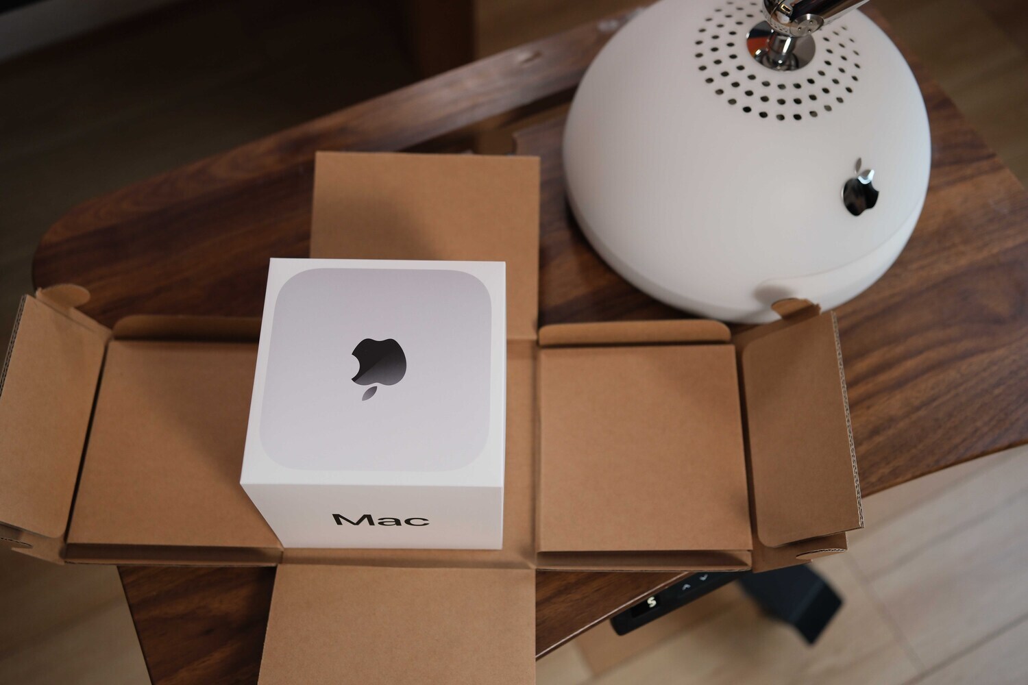
Hi guys, in this article we are going to share about my progress of renovating & renewing the Apple’siMac G4, which was released 23 years ago.

For those who hasn’t figured it out yet, this is a computer that was produced 22 years ago by Apple,called iMac G4. The time this genious appeard, it was something truly special that completely changed people’s mind and their imagination about a desktop computer.

A design where technology and industrial art meet
In the past, when computers on the market were still in traditional shapes, Apple chose to challenge themselves with a whole new idea.A combination between technology and industrial art, which inspired by sunflowers, to become this unique computer. iMac G4 existed for one and a half years with 3 versions:15/17/20 inches, of which 15 inches was the most popular version. The remaining 17 inches and 20 inches are extremely rare because there were only more than 2000 produced at that time. It’s equipped with a 180-degree rotating screen arm, a high resolution LCD screen, and all the remaining components are integrated under the base. A special thing about this arm is that when you raise or lower the screen, the viewing angle will not change, because inside it’s 2-way linked.Not just extremely good but also practical both idea and design, as you can see nowadays the common screen arms you are using will not be able to do the same thing.
 And the operating principle of this arm still applies to today's Apple screens, the external design may be different but the operating principle remains the same.
This gorgeous technology has and still bringing lots of emotions
Until now, after 22 years, I still find it magnificent and fashionable. If there was a machine today made with a design like this, fashionable like this, but powerful inside, I would definitely still buy it at any price. And that is also the reason why I want to do something, which is to renovate this machine, keep this design and make it stronger, more practical at the present time.
 That’s how my project started.
With the goal of making new iMac but same design 22 years ago, using latest configuration today. Inside equiped with a mini M4, then I will leave it on the counter for my team to use. I spent many days researching and watching all the videos of our foreign friends doing this project, to gain more experience, to learn. And also through these processes, to see that I’m not satisfied with any upgraded version because it’s too different from my criteria and desires.
I’ve listed the work items that need to be prepared and done for you guys:
- Disassemble G4 and M4, get the design statistic
- Measure & redesign according to the original screw position
- Redesign the disk tray system
- Replace new screen Panel
- Remake connection ports
- Assemble and complete
- All components will be listed at the end of the artical
Disassemble the parts of iMac G4(2002) and Mac mini M4 (2024)
This is the internal images of both machines that 22 years apart. To disassemble the G4 and Mini M4, you can watch some videos online, it’s actually pretty easy, wherever there are screws, just remove them all and you're done. It's not too difficult, Mac Mini M4 is very easy to disassemble because nowadays Apple makes each module separately.

This is all the insides of the iMac G4. All the internal components look big and bulky but are arranged very scientifically and neatly. At that time, semiconductor technology was not as developed as it is now, so it was natural that the components were larger. However, the neatness in the arrangement and scientific position of each component is still very typical of Apple.
 The screen shell, my G4 died and could not be used anymore, it was also quite old so it had to be redone a lot. This screen part is the most time-consuming part. Not the time to make it but the time to change many different solutions.
 The small components inside are almost too old, some parts are aging like the speakers and rubber seals.
 This is its power supply, a 12V isolated power supply. I will show you later that the power supply ofthe M4 today is very different.
 Underneath its plastic shell is a metal case, really heavy and sturdy.Do you see that jagged shape ring? That's pressed into the white plastic outer shell. Once assembled, it's very sturdy and cannot be moved.
 The bottom base, where the mainboard is located.
 This is the DVD and HHD drive cluster.
 The best thing is that the arm is 22 years old but still, shiny and works so well.
 These are mainboards of iMac G4and Mini M4 today.
 The types of connections then and now, through images I’ve shown, you can also feel how technology has changed over the years. But Apple's design mindset and aesthetics in the products are still there.
Disassemble parts of Mac mini M4
The mini M4 is easy to disassemble, you just need to unscrew all the screws and you're done lol.
 This is the entire inside of Mac MiniM4, you will see a 12V power supply, mainboard, wifi cluster and cooling fan. Quite simple and neat.
 This is the power supply of Mac mini M4, it has parameters of 12.6V and 12A. It is a huge parameter, but you can rest assured. Apple always makes redundancy and safety in important parts, and because this power cluster is used for even the highest configurations with the entire screen, so they made this power cluster.
 As for the Base version or a slightly higher configuration, it does not consume more than 65W for all tasks and screens. If you only use a secondary screen with base version, it consumes less than 30W.

So you only need a 12V 3A or 4A power supply for this project to use. I have hooked it up and used it, monitored it for a while before carrying on, you won’t have to worry.
 This is the mainboard of Mac mini M4, you will notice that there are 212V power poles printed there. You should check the correct direction -+ and hook up the wires to install the new position you like. You should keep the wifi cluster and cooling fan intact for neatness because they are assembled together. In the picture, I only disassembled each part just to take pictures.
Coming up with ideas and designing the internal parts
The software I often use to design and sketch ideas is Shapr3D, I rate this as a very easy-to-use, accessible and 3D-manipulating software. Suitable for those who using 3D printing, carrying out small and medium DIY projects.

I’ve made instructional videos on how to use this software on my YouTube channel. If you are interested, you can go there to watch and try it out. I think after 5 videos, you can use and master it. As for the user account, you can buy it from edu account selling services, or anyone with an edu email can register for a free 1-year trial.
 When you download my design file,you will see things like images above. Those are all the drawings related to this project. I will introduce each part for you to understand.
 First is the screen part, I redraw it so that I can make a new one myself. Because I was passive in the process of trying to put the new panel into the old frame of the G4. So I redraw it to do it myself for convenience.
 This drawing I made for a 15-inch 4k panel with 16:10 ratio, so if anyone wants to use that size, you can use it.
 This part consists of 3 parts, the back, the front, and the mica border. You can cut the mica and grind the edges to look like the original. Because this size will exceed the printing size of your machine, you should send it to a printing service for more convenience. You can choose to print ABS or if you like, CNC it with aluminum might be cool too.
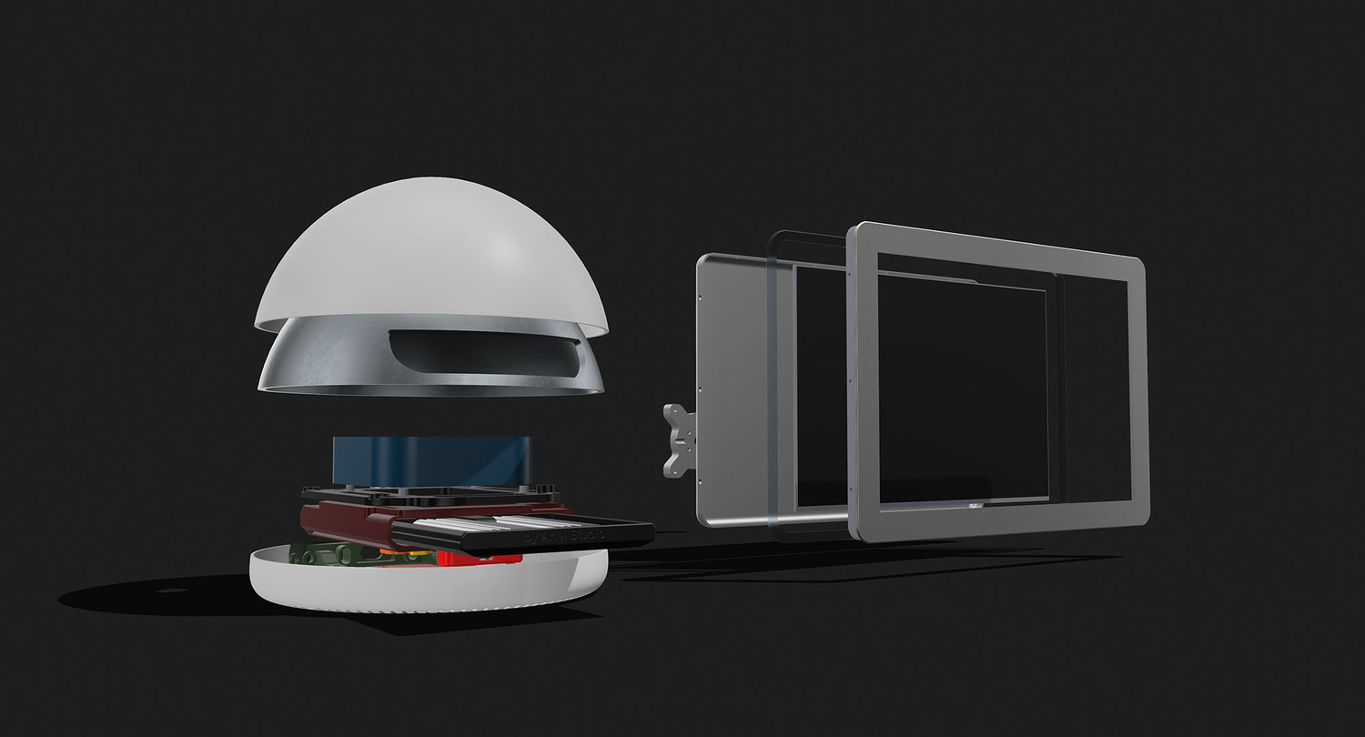
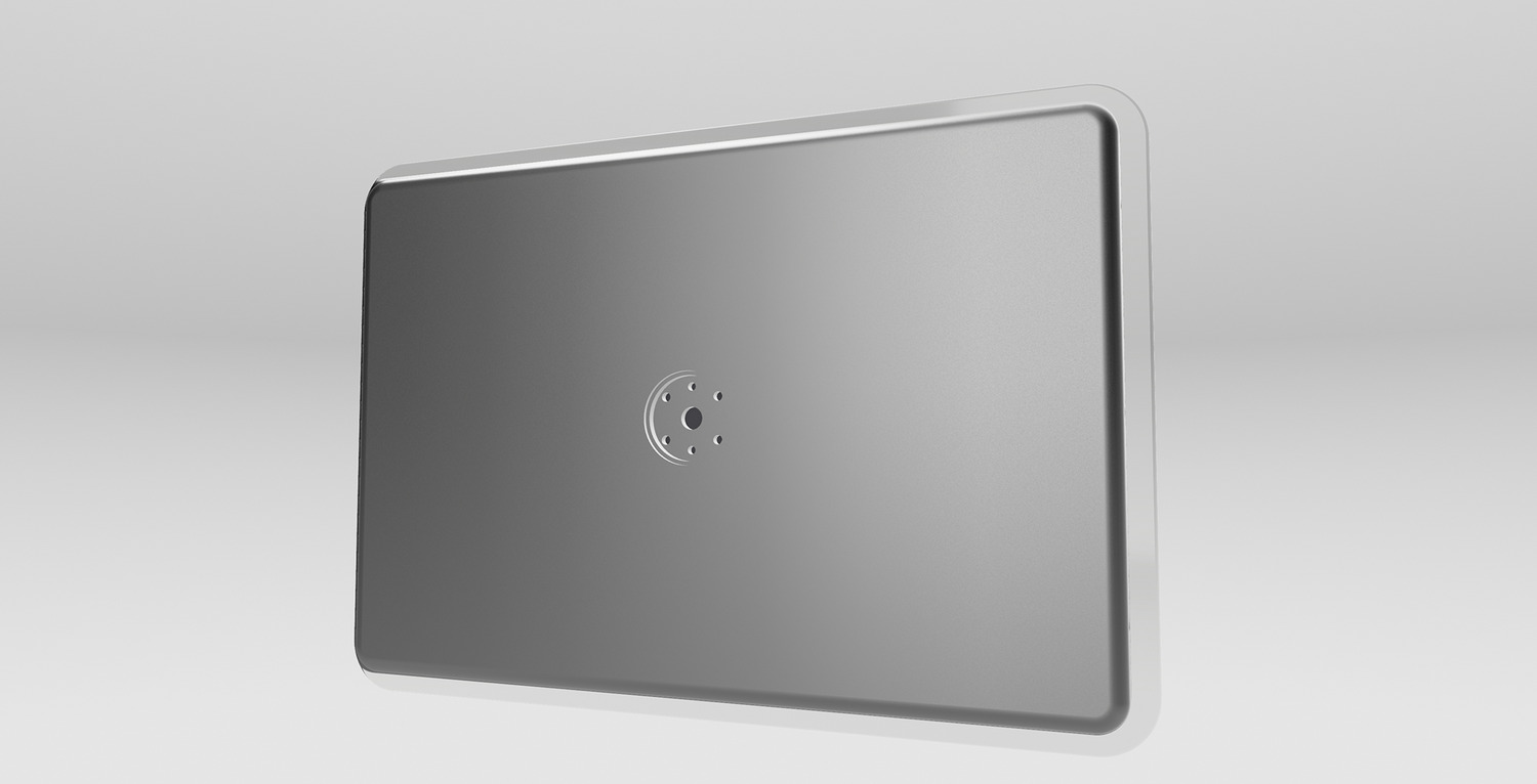
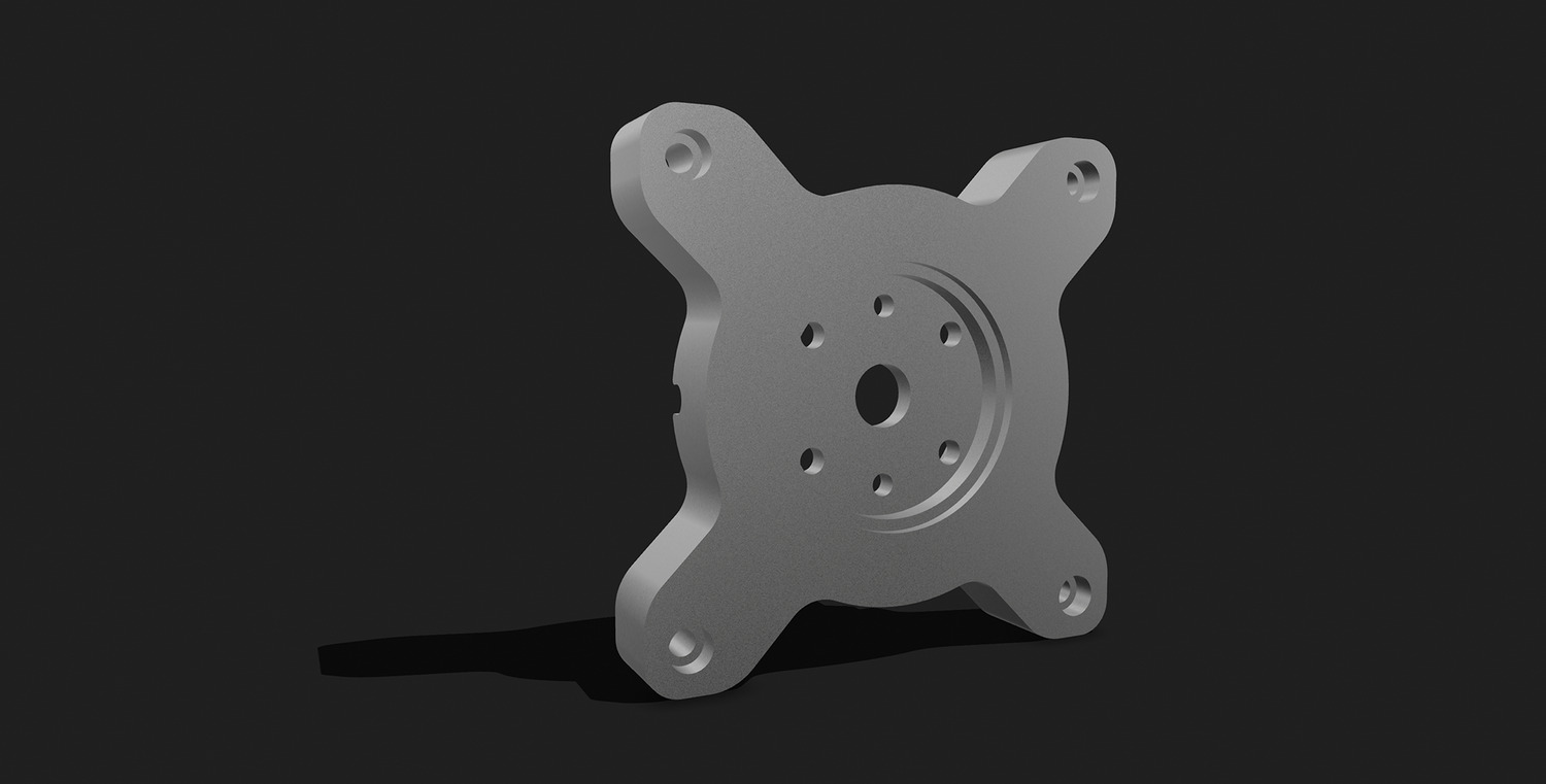 This is a conversion mount for those who do not want to renovate and reuse the G4 screen but want to mount a mobile screen. I made it to use with a 75mm VESA mount, so if you want to use it, just follow that. One side will screw into the arm, the other side will screw on to the screen.
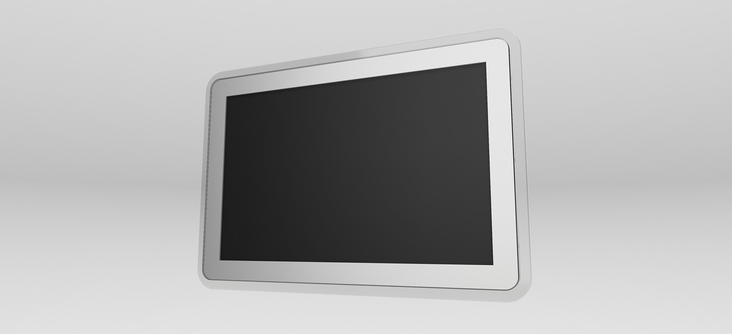
 Mounted on the secondary screen, it will look like this. I am testing to mount a 17-inch monitor with a 75mm VESA hole.
 This is the bottom part, this part is printed to mount the power circuit of the M4, you print it out and mount it on the screw holes of the available aluminum base and the top part is to mount the power board.
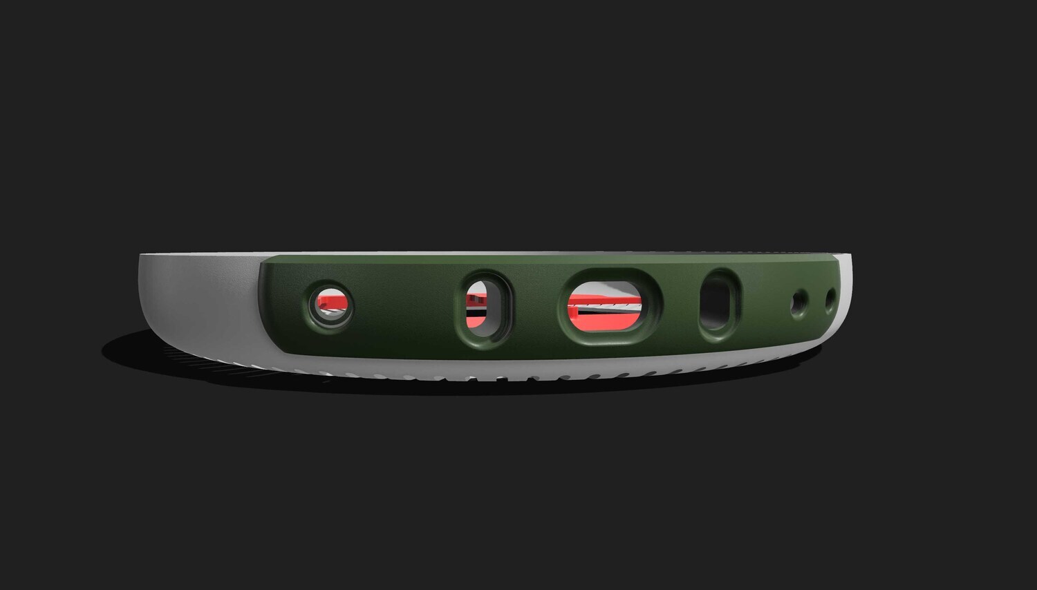 The back cover, I rebuilt it with power port number 8, 2 typeC ports, DC power port 5mm-2.1 and 2 buttons for power and to press to open the sliding tray.
 The slightly more complicated partis this sliding tray assembly, it looks complicated but actually also easy to print and assemble. I also made a separate video for you to assemble this. You just print it out and look at the picture, maybe you can assemble it.
 The steps and assembly methods are divided by color so that you can easily visualize. This limit switch returns signals to the motor control circuit.
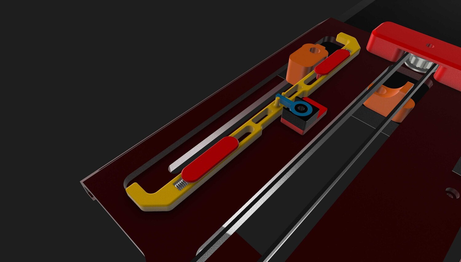 In this structure, you can just print it out, take a look and ypu’ll know how to assemble it yourself. There are 2 springs in here to attach to the groove, so I took the springs inthe switches of the mechanical keys hihi.
 About the notes of the 3D printing part, you just need to choose the right printing material, so that it can be more durable and stable. For the details that need to be strong or hard, you can choose PETG GF like me for ease, which is also apopular and easy-to-print material. Or you can print the whole thing with ABS for sure. As in the video and this project, I printed the bottom and top base with PETG GF, the rest I printed with Bambulab's PLA CF.
Let's get started assembling everything!
 First, we will open this arm, it's not difficult. There are videos on the internet with instructions on how to open it, so you can refer to them. I opened everything up, cut off all the old cable systems, re-greased them, then re-routed TypeC cable for use with the TypeC separate screen.
 After struggling for a while, I was able to get TypeC cable through. As you can see in the picture, I removed the plastic cover of the cable head, because if I kept it, it would be too big to go through the original hole. I even had to mill the inner core a little larger so that it easier to pass through. If you want to use a TypeC cable, you can use this method. Or there’s another way, you can use a flat HDMI cable, the 2 ends can be removed, which will be easier, but if you use an HDMI cable, you will need to run an additional power cord to supply the screen.
 Remember to print out these 2 parts first, these are easy to assemble first. Red is for the mainboard, black is the bottom partto mount the power board.

Remove the power board of the Mini M4, after soldering the power wire, mount it on top as images I’ve shown. Fix it with 4 screws to the base, where I’ve already prepared the spot, you can use the M3 sawtooth screws that go into the plastic. On the power board there is a DC -+ line and 3 signal wires, if you like you can extend those 3 wires, or not, it's okay, just need 2 wires for the power to go up.
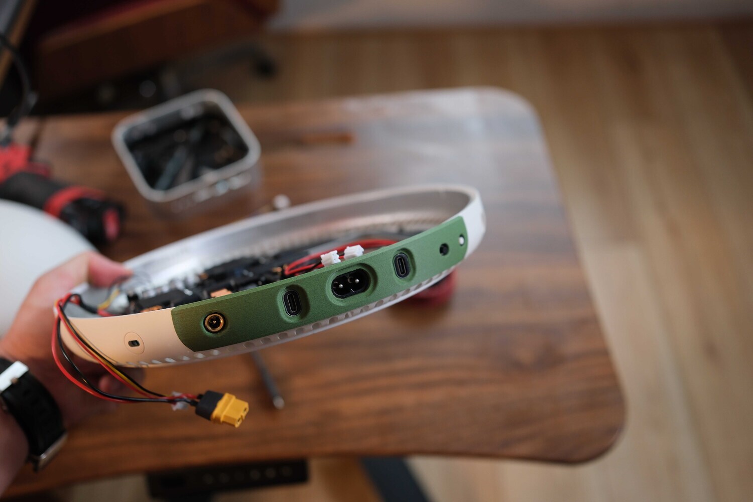
Next on this base is the mask of connection ports at the back. I redid it to only have the power port number 8, 2 TypeC ports, 2 buttons and 1 DC 5mm port to use the battery instead of electricity when needed.
 Connect DC port to the 12V output pin of mainboard, wire 2 buttons to the jack to wait to connect to the top. One button is for starting, one button is for controlling the SSD tray. As you can see, to mount the mask like I designed, you have to remove a plastic part on the back, position of the old connection ports.

Next is the top part, print this sheet out and mount it similarly with the 4 available screw holes on the mainboard. You keep the fan cluster, wifi and cable ports intact. Not mounting the 3.5 port and the speaker is okay.
 In the front are 2 TypeC 10Gbs ports, in the back are 3 Thunderbolt 40Gbs ports. I use 2 front ports to connect the wires to the SSD tray I made.
 There are 3 Thunderbolt ports on the back, so I use 2 ports to connect below the connection mask, the middle port is for the screen, through TypeC wire of the arm I made above.
 After assembling, you put it in the G4 case, it will look like this, right at the 4 available screw positions so there won’t be any mistake (the picture I illustrated sometimes has wrong plastic color because I worked on this for a long time, so you just need to pay attention to the content and position).
 This is the entire wire connected from the mainboard down. Including 2 extended Thunderbolt wires, DC power jack to connect to the power board, the other 3-pin jack is the signal of power board (not needed is okay), the yellow and green wires are the power button wires that I connect down to connect to the button at the back.
 Next is the sliding tray system, this tray is used to store things and also has 2 positions to mount the SSD drive. I designed it for the Lexar E300 drive, which is only 10Gbs speed but still suitable because the 2 front ports are also 10Gbs, and it’s also to reduce heat if used for along time.
 This part is also very simple to assemble, just print out the entire file and look at the 3D image, I’m sure that you can assemble it.
 This is the bottom side, where motor, trip switch, trip control system and stops are installed. As for the control circuit, to make it simple, you can use a 2-way limit switch circuit instead of using a control chip like me.

 Then you continue to install it right in the DVD tray position, with the screw holes available on the red frame, you align it straight with the DVD tray and then screw it down.
 The 2 light-colored cables are TypeC cables attached to the sliding tray, I cut off the outer shell to make it easier for moving, wrapped it with electrical tape, after installing it, you apply a little grease and it's good to go. These 2 wires are the wires that come with Lexar SSD box, I drew according to that wire so you can use it to get the right size.
 It might looks complicate but there are only 3 clusters like this, you can assemble each part and then just reassemble it according to the old screw holes.
 When installing this sliding tray, you pull it out to keep an eye on the inside, then screw the screws according to the predetermined holes on the red case for the most accurate. The remaining parts, such as mounting the arm on the case, you just need to reassemble it as how you disassemble it.
 If everything goes smoothly, you will have an iMac like this, of course the screen part above is not finished yet. For this part, there will be 2 options for you to choose from. 1 is to completely renew it, 2 is to attach a mobile screen.
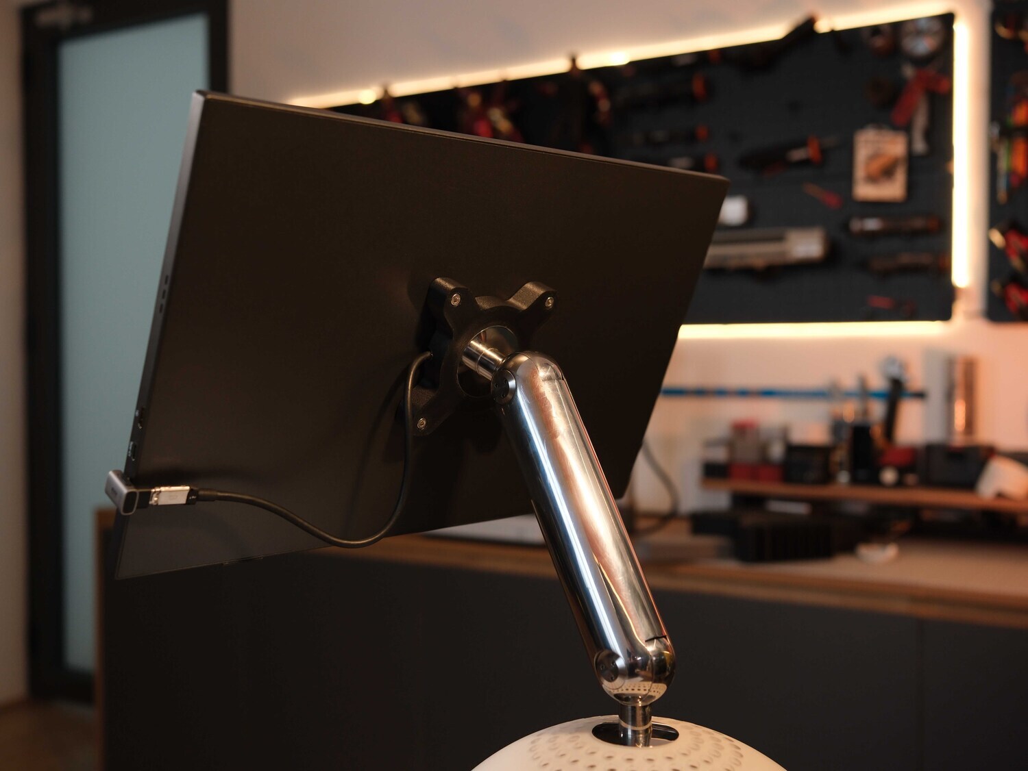
 If you choose to attach an external mobile screen, you simply need to print the VESA mount file I drew above, attach it to the arm and attach the screen, done! It will looklike this.
 If you choose to use a mobile screen, just attach it via the connected TypeC port, and that's it. Start up and enjoy the results, but if you want to continue trying hard with me, then we'll continue. Renew a screen, based on the original design I drew.
To start remaking this screen. I designed it to include 3 parts, the back, the front and the mica border. You can choose to send it to a printing service outside because this size is larger than the size of my personal printer, the back and the mask can be printed with white ABS, then sanded and painted again, or if you like, you can have it CNC aluminum. Here I chose the 3D printing option using SLA technology and ABS material. After printing, to make it more beautiful, you can sand it again, then repaint it.
 This mica border is laser cut according to the design file, the outer corners are polished to look like the original. Then rub it with cana or something similar,it will look like this.
 About the screen panel, here I use 16-inch size with 16:10 ratio because I find this size and ratio balanced compared to the other sizes I tried. Since the measurements are accurate, you can try it on and finish.

Then attach the back part to the arm, attach the driver circuit for the screen. Because today's components are much lighter than the original, I have increased its weight with iron weights, you can find them on e-commerce sites with the keyword "gusset plate". This gusset plate is made of iron, so if you want to use it for a long time, you should repaint it or treat it to avoid rust.
 This is the back part of new panel, 16-inch size and uses a 40-pin port.
 Then attach it to the arm, screw it like when you removed it.
 And that’s how we’ve completed the screen part. After finishing this part, I spent a long time front of it, admiring it. I felt that it’s truly magnificent and satisfying.
 This is probably the sexiest angle of the G4 that I have seen, seeing everything, the shiny arm, the cute base and the sexy screen.

Wish you guys success and always be creative in your own creation. Below are the videos I recorded during this process for you guys to follow and refer to. Thank you guys, have fun!
-----------------------

If you find my project and ideas interesting, creative, and valuable, you can support me by donating via PayPal: duongdesign.cip@gmail.com. Your support means a lot—it’s a way to appreciate creative work and contribute to future projects. Wishing you all success and great achievements!
If anyone is interested, feel free to send your questions or discuss your projects in the Group Chat. Telegram
COMPONENT LIST (For reference only. You can use the images or names and search for them in your country.)
- Design file here
- Panel display 16:9 4k Resolution
- Box SSD Lexar E300 (2pcs - optional)
- SSD Lexar 1Tb (2pcs - optional)
- Cable TypeC Thunderbolt 3 or 4 - 1m for Arm (1pcs)
- Cable TypeC Thunderbolt 2 - (2pcs)
- Type C Conector (2pcs)
- TypeC Conector (2pcs)
- Button (2pcs)
- Jack DC 5mm (1pcs)
- AC Port (1pcs)
- Jack XT60 (1pcs)
- Jack 2pin or 3pin (2pcs)
- Motor (1cái)
- Belt (1pcs)
- Puly (1pcs)
- Limit Switch (1pcs)